How Data Travels Across the Internet: The Journey of a Packet
You just hit send on a message to your friend halfway across the world. In less than a second, they receive it. You stream a 4K video, download a massive file, or join a video call with someone on another continent. It all feels instant, magical even. But have you ever wondered what actually happens in that split second?
Your message does not travel as one continuous stream. Instead, it gets chopped into tiny pieces, sent through dozens of computers you have never heard of, potentially taking different routes, and then reassembled perfectly on the other side. Sometimes these pieces arrive out of order. Sometimes they get lost. Sometimes they take a detour through three different countries to reach a destination in the same city.
Understanding how data actually moves across the internet is not just fascinating trivia. It is the foundation for debugging network issues, building scalable applications, optimizing performance, and making smart architectural decisions. Every senior engineer should know this cold. Let us pull back the curtain on one of the most elegant systems ever designed.
What Problem Does Packet Switching Solve?
Before we dive into how data travels today, we need to understand what came before and why it was not good enough. In the early days of communication networks, we used something called circuit switching. This is how telephone networks worked, and honestly, it made perfect sense at the time.
Circuit Switching: The Old Way
When you made a phone call, the network established a dedicated physical circuit between you and the person you were calling. Think of it like this: imagine connecting two tin cans with a string. That string is yours and yours alone for the entire duration of the call. Nobody else can use it. The connection stays open whether you are talking or sitting in silence.
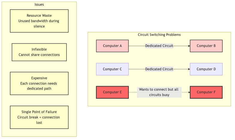
Diagram 1
This worked fine for voice calls, but it had serious problems for computer networks:
-
Massive waste of resources: If you are reading a webpage, you are not constantly sending or receiving data. You read for 30 seconds, then click a link. During those 30 seconds of silence, your dedicated circuit just sits there, completely unused, but no one else can use it either.
-
Expensive and inflexible: Setting up a dedicated circuit between every pair of computers that might want to communicate? Imagine the cost. Imagine the complexity. It simply did not scale.
-
Single point of failure: If any part of your dedicated circuit got damaged or went down, your entire connection was toast. In a military context (where the internet was born), this was unacceptable. What if a city got attacked and took out key communication lines?
-
Slow setup time: Establishing a circuit could take seconds or even minutes. For quick, bursty data transfers, this overhead was ridiculous.
Why was a new solution needed?
In the 1960s, the Cold War was in full swing. The U.S. military needed a communication network that could survive a nuclear attack. Paul Baran at RAND Corporation and Donald Davies at the National Physical Laboratory independently came up with the same revolutionary idea: what if instead of dedicated circuits, we broke messages into small chunks and sent each chunk independently?
This was the birth of packet switching, and it changed everything.
Real World Analogy
Think of data transfer like shipping a large piece of furniture across the country:
Circuit Switching is like renting an entire highway lane exclusively for your furniture truck. You reserve that lane, and it is yours from start to finish. Even if your truck breaks down and sits there for hours, nobody else can use that lane. Super wasteful, right? But hey, at least you know your furniture will take the exact same route.
Packet Switching is like breaking your furniture into smaller boxes, giving each box a shipping label with the destination address, and sending them through the regular postal system. Some boxes might go through Chicago, others through Dallas. Some might travel by plane, others by train. Some might arrive out of order (your table legs arrive before the tabletop). But in the end, all the boxes reach the destination, and you can reassemble your furniture.
The postal service (the internet) can handle millions of packages (packets) simultaneously because they share the same infrastructure. Way more efficient. Way more resilient. If one route gets blocked, packages just take another route.
How Does Packet Switching Work?
Packet switching flips the circuit switching model on its head. Instead of establishing a dedicated path before communication, data gets divided into small, self contained units called packets. Each packet carries everything it needs to reach its destination: the actual data, the sender's address, the recipient's address, and some extra information for error checking and ordering.
The core idea is beautifully simple:
- Break data into packets: Your email, video stream, or file download gets divided into small chunks (typically 1,500 bytes or less)
- Add addressing information: Each packet gets wrapped with headers containing source and destination addresses
- Send independently: Packets get released into the network and travel independently
- Route dynamically: Each router along the way decides the next best hop for that packet
- Reassemble at destination: The receiving computer collects all packets and puts them back in the correct order
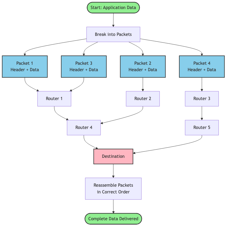
Diagram 2
Why this approach?
This solves all the problems of circuit switching:
- Efficiency: Network links are shared among many users. When you are not sending data, someone else can use that bandwidth.
- Resilience: If a router fails, packets automatically route around the failure. No single point of failure.
- Scalability: Adding new computers to the network is trivial. They just need an address.
- Speed: No setup time required. Start sending packets immediately.
Key innovations that made this work:
-
Statistical multiplexing: Multiple data streams share the same physical links. The network buffers packets briefly at each router and forwards them as capacity allows.
-
Store and forward: Routers receive entire packets, check for errors, and then forward them. This allows error detection at each hop.
-
Best effort delivery: The network tries its best to deliver packets but makes no guarantees. Higher level protocols (like TCP) handle reliability.
-
Decentralized routing: No central authority controls the network. Each router makes independent decisions based on local information.
The Evolution of Data Transfer
How We Got Here: A Historical Journey
Understanding the history helps you appreciate why the internet works the way it does today. Every design decision was a response to real problems people faced.
1960s: The Birth of Packet Switching
Before the internet, computers were isolated islands. In 1961, Leonard Kleinrock published his thesis on queuing theory, proving that packet switching was more efficient than circuit switching for bursty data traffic. In 1964, Paul Baran designed a distributed network for military communications that could survive attacks. Independently, Donald Davies coined the term "packet" in 1965.
The key insight: breaking data into small, independently routed packets created a network that was robust, efficient, and scalable.
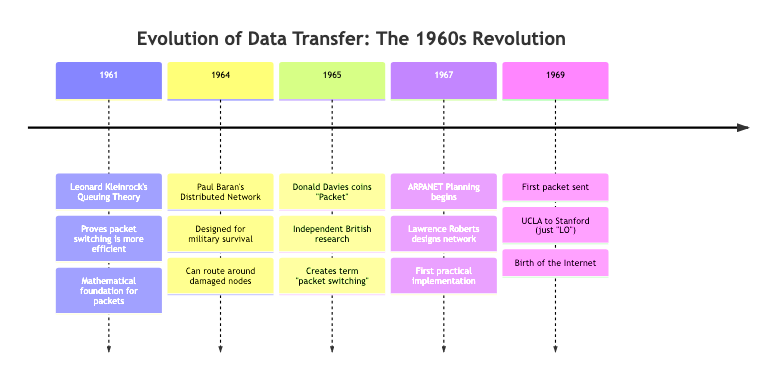
Diagram 3
1969: ARPANET - The First Packet Switched Network
On October 29, 1969, the first message was sent over ARPANET between UCLA and Stanford Research Institute. They tried to send the word "LOGIN" but the system crashed after "LO." Even the first internet message was literally "Lo" (as in "Lo and behold"). Poetic, right?
ARPANET initially connected four universities. The network used Interface Message Processors (IMPs), which were essentially the first routers. These refrigerator sized computers would receive packets, store them, check for errors, and forward them to the next IMP.
1970s: Growing Pains and Protocol Wars
As ARPANET grew, problems emerged. Different networks used different protocols and could not talk to each other. In 1974, Vint Cerf and Bob Kahn published a paper introducing TCP/IP (Transmission Control Protocol/Internet Protocol). This was the "internetwork protocol" that could connect different networks together. Hence the name: internet.
The genius of TCP/IP was splitting responsibilities:
- IP handles addressing and routing (getting packets from A to B)
- TCP handles reliability, ordering, and error correction (making sure data arrives intact)
1983: The Big Switch
On January 1, 1983, ARPANET officially switched from NCP (Network Control Program) to TCP/IP. This is considered the birth of the modern internet. Now different networks could interoperate using a common protocol.
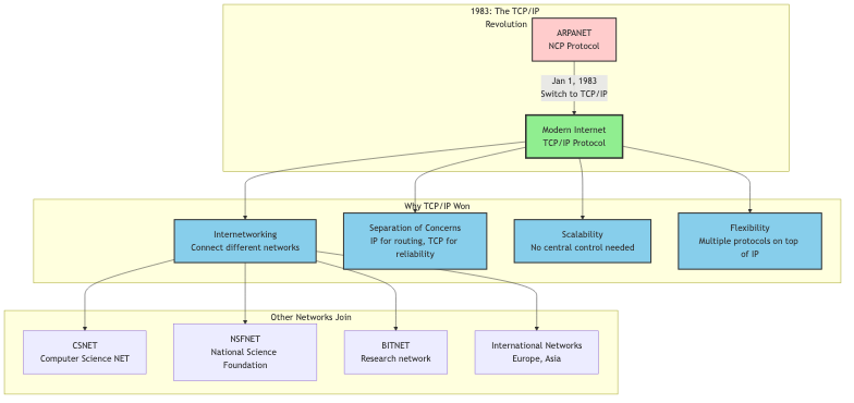
Diagram 4
1990s: The World Wide Web and Exponential Growth
In 1989, Tim Berners Lee invented the World Wide Web at CERN. This was not the internet itself, but an application running on top of the internet (HTTP/HTML). Suddenly, the internet was not just for academics and military folks. Regular people wanted in.
The number of internet hosts exploded:
- 1990: 313,000 hosts
- 1995: 6.6 million hosts
- 2000: 93 million hosts
This growth stressed the packet switching infrastructure. Routers got faster. Fiber optic cables replaced copper. New protocols emerged to handle different types of traffic.
2000s: Mobile, Cloud, and Streaming
The rise of smartphones, cloud computing, and video streaming created entirely new challenges. Suddenly, billions of devices needed to send packets constantly. Video streaming required predictable bandwidth and low latency.
Technologies evolved:
- CDNs (Content Delivery Networks): Cache content closer to users
- Multicast: Send one packet to many recipients simultaneously
- QoS (Quality of Service): Prioritize certain types of traffic
- IPv6: Expand the address space from 4.3 billion to 340 undecillion addresses
2010s to Today: The Modern Internet
Today's internet is a beast. We transfer exabytes of data daily. The core innovations from the 1960s still apply (packets, routing, best effort delivery), but we have added layers of optimization:
- Edge computing: Process data closer to the source
- HTTP/3 and QUIC: Reduce latency by improving how packets are handled
- 5G networks: Deliver gigabit speeds to mobile devices
- Submarine cables: 99% of intercontinental traffic travels through undersea fiber cables
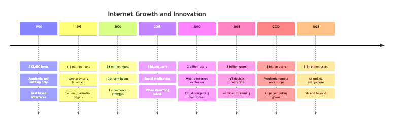
Diagram 5
The fundamental concept remains unchanged: break data into packets, send them independently, reassemble at the destination. But the scale, speed, and sophistication have increased astronomically.
Visualizing How Packets Travel
Let me walk you through exactly what happens when you request a webpage. We will follow a single packet on its journey from your laptop to a web server and back.
Step by step walkthrough:
Step 1: Application Layer Creates Data
You type a URL into your browser and hit Enter. Your browser needs to fetch the webpage. It creates an HTTP request: "GET /index.html HTTP/1.1"
- What happens: The application (browser) generates the data that needs to be sent
- Why it happens: Applications do not deal with packets directly. They work with logical data streams
- State change: HTTP request created → Ready to be packetized
Step 2: Data Gets Broken Into Packets
Your operating system's network stack takes that HTTP request and breaks it into chunks. Each chunk becomes the payload of a packet. For small requests, you might only need one packet. For large file uploads, you might need thousands.
- What happens: Data divided into packet sized chunks (usually 1,500 bytes or less to fit in an Ethernet frame)
- Why it happens: Networks have a Maximum Transmission Unit (MTU). Packets must fit within this limit
- State change: Continuous data stream → Discrete packets
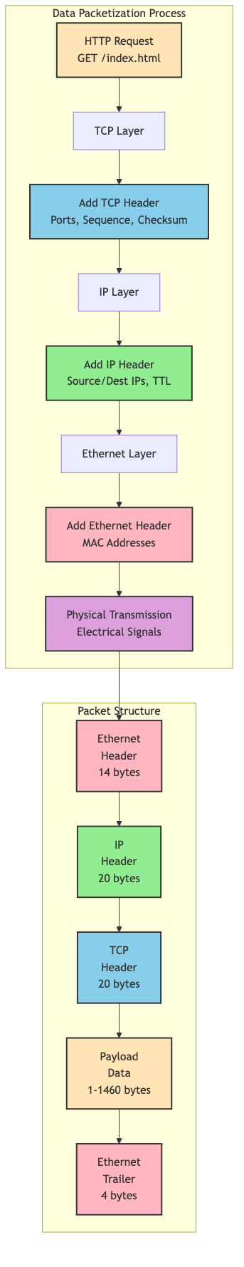
Diagram 6
Step 3: Adding Headers (Encapsulation)
Each packet gets wrapped in multiple layers of headers, like putting a letter in an envelope, then putting that envelope in a shipping box, then putting that box in a larger container.
Layer 4 (Transport Layer): Adds TCP header with:
- Source port (your browser's random port, like 54321)
- Destination port (web server's port, usually 80 or 443)
- Sequence number (which piece of data is this?)
- Checksum (for error detection)
Layer 3 (Network Layer): Adds IP header with:
- Source IP address (your computer's IP, like 192.168.1.100)
- Destination IP address (web server's IP, like 93.184.216.34)
- Time to Live (TTL) - maximum number of hops before the packet dies
- Protocol (TCP, UDP, etc.)
Layer 2 (Data Link Layer): Adds Ethernet header with:
-
Source MAC address (your network card's physical address)
-
Destination MAC address (your router's MAC address)
-
What happens: Each layer adds its own header with addressing and control information
-
Why it happens: Each layer has different responsibilities and needs different information
-
State change: Raw data → Fully addressed packet ready for transmission
Step 4: Packet Leaves Your Computer
Your network card converts the digital packet into electrical signals (or radio waves if Wi Fi) and sends it to your router.
- What happens: Physical transmission of bits onto the network medium
- Why it happens: Digital data needs to become a physical signal to travel across wires or air
- State change: Digital packet → Physical signal on the wire
Step 5: Router Makes Forwarding Decision
Your home router receives the packet. It looks at the destination IP address and checks its routing table to decide where to send the packet next.
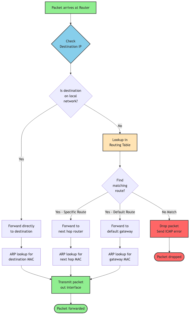
Diagram 7
Your router sees the destination IP (93.184.216.34) is not on your local network. It strips off the Ethernet header (which was just for getting from your computer to your router) and forwards the packet to your Internet Service Provider (ISP).
- What happens: Router examines destination IP and consults routing table
- Why it happens: Routers connect different networks. They need to determine the next hop toward the destination
- State change: Packet enters router → Packet forwarded to next hop
Step 6: Hopping Through the Internet
Now your packet enters the wild internet. It bounces from router to router, each one making an independent decision about where to send it next. A typical path might look like:
- Your home router
- ISP's local router
- ISP's regional router
- Internet backbone router
- Tier 1 network router
- Destination ISP's router
- Web server's local router
- Web server
Each hop decrements the TTL (Time to Live) counter. If TTL reaches zero, the packet gets dropped. This prevents packets from circulating forever in routing loops.
- What happens: Packet traverses multiple routers, each forwarding it closer to the destination
- Why it happens: No single router knows the complete path. Each router only knows the next best hop
- State change: Multiple router hops → Packet approaches destination network
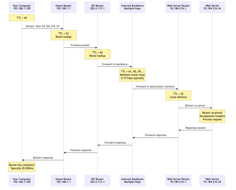
Diagram 8
Step 7: Arriving at Destination
The packet finally reaches the web server's router. This router recognizes the destination IP as one of its local machines and forwards the packet to the web server's network card.
- What happens: Final router delivers packet to destination host
- Why it happens: Packet has reached its destination network
- State change: Packet in transit → Packet delivered to destination machine
Step 8: Decapsulation and Reassembly
The web server's network stack peels off the headers in reverse order:
- Strip Ethernet header (Layer 2)
- Strip IP header (Layer 3)
- Strip TCP header (Layer 4)
- Deliver payload to application (web server software)
If this was part of a larger data stream, TCP reassembles packets in the correct order using sequence numbers.
- What happens: Each layer strips its header and passes data up to the next layer
- Why it happens: Headers were added for transmission. Now we need the original data back
- State change: Packet with headers → Original application data
Step 9: Server Processes Request and Sends Response
The web server reads your HTTP request, processes it, and generates a response (the HTML for the webpage). This response gets packetized and travels back to you through the same process in reverse.
- What happens: Server generates response and sends it back as packets
- Why it happens: Request/response cycle completes
- State change: Request received → Response sent

Diagram 9
Step 10: Your Browser Receives and Displays
Your computer receives the response packets, reassembles them into the complete HTML document, and your browser renders the webpage.
- What happens: Complete response reassembled and displayed to user
- Why it happens: User requested a webpage, now they see it
- State change: Packets received → Webpage displayed
This entire journey breaking data into packets, sending them across multiple routers, reassembling them happens in milliseconds. Sometimes hundreds of milliseconds if the server is far away, but still incredibly fast considering the complexity.
The Anatomy of a Packet
Let me show you exactly what is inside a packet. Understanding the structure helps you debug network issues and make better design decisions.
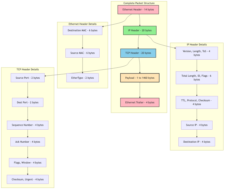
Diagram 10
A typical packet has three main parts:
1. Headers (20-60 bytes typically)
Multiple headers stacked on top of each other, each added by a different layer:
Ethernet Header (14 bytes):
- Destination MAC address (6 bytes): Physical address of next device
- Source MAC address (6 bytes): Physical address of current device
- EtherType (2 bytes): What protocol is inside? (Usually IP)
IP Header (20-60 bytes, typically 20):
- Version (4 bits): IPv4 or IPv6
- Header length (4 bits): How long is this header?
- Type of Service (8 bits): Priority and QoS hints
- Total length (16 bits): Size of entire packet
- Identification (16 bits): Which fragments belong together?
- Flags and fragment offset (16 bits): For reassembling fragments
- Time to Live (8 bits): Maximum hops before death
- Protocol (8 bits): What is inside? (TCP = 6, UDP = 17)
- Header checksum (16 bits): Error detection for the header
- Source IP address (32 bits): Where did this come from?
- Destination IP address (32 bits): Where is this going?
TCP Header (20-60 bytes, typically 20):
- Source port (16 bits): Application port on sender
- Destination port (16 bits): Application port on receiver
- Sequence number (32 bits): Position in data stream
- Acknowledgment number (32 bits): Next expected byte
- Data offset (4 bits): TCP header length
- Flags (12 bits): SYN, ACK, FIN, RST, etc.
- Window size (16 bits): Flow control
- Checksum (16 bits): Error detection
- Urgent pointer (16 bits): Rarely used
- Options (0-40 bytes): Optional extensions
2. Payload (1-1,460 bytes typically)
This is your actual data. For an HTTP request, this might be "GET /index.html HTTP/1.1\r\nHost: example.com\r\n\r\n"
The maximum payload size depends on the MTU (Maximum Transmission Unit):
- Ethernet MTU: 1,500 bytes
- Minus IP header: 20 bytes
- Minus TCP header: 20 bytes
- Maximum TCP payload: 1,460 bytes
3. Trailer (4 bytes for Ethernet)
Some protocols add a trailer for error detection:
- Frame Check Sequence (FCS): CRC checksum of the entire frame
Total typical packet size: 54 bytes overhead + payload
For a 1,460 byte payload, that is only 3.7% overhead. Pretty efficient!
How Routers Make Decisions
Routers are the unsung heroes of the internet. They receive packets, figure out where to send them next, and forward them billions of times per second across the entire internet. Let me show you how they actually work.
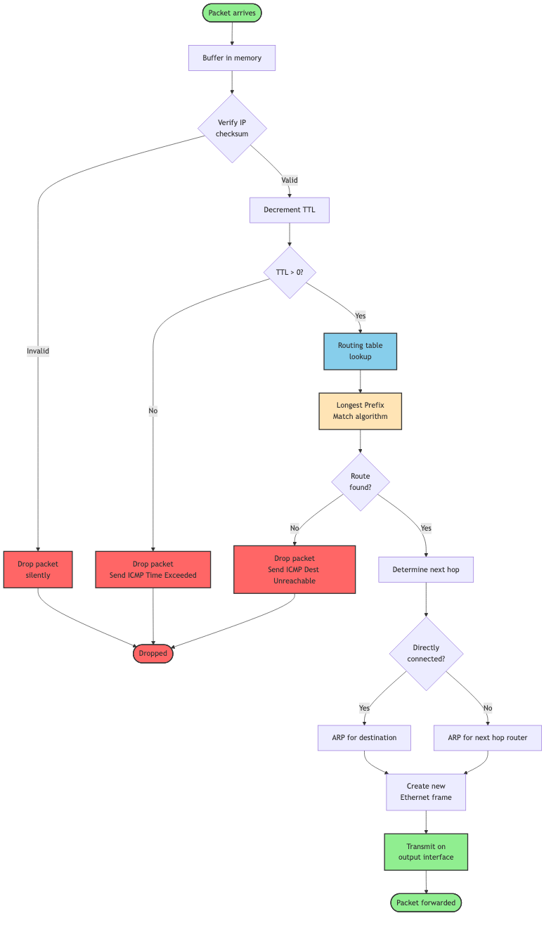
Diagram 11
Step by step router operation:
Step 1: Packet Arrives
A packet arrives on one of the router's interfaces (physical ports). The router buffers it in memory.
Step 2: Checksum Verification
The router verifies the IP header checksum to ensure the header was not corrupted in transit. If corrupted, the packet gets dropped silently.
Step 3: TTL Decrement
The router decrements the TTL (Time to Live) field by 1. If TTL reaches 0, the packet gets dropped and an ICMP "Time Exceeded" message gets sent back to the source. This prevents infinite routing loops.
Step 4: Routing Table Lookup
This is the critical step. The router examines the destination IP address and looks it up in its routing table. The routing table contains entries like:
Destination Network    Next Hop         Interface    Metric
0.0.0.0/0             203.0.113.1      eth0         1      (default route)
192.168.1.0/24        0.0.0.0          eth1         0      (directly connected)
10.0.0.0/8            198.51.100.1     eth2         5      (via gateway)
The router finds the most specific match (longest prefix match) for the destination address. If the destination is 10.0.5.27, it matches 10.0.0.0/8.
Step 5: ARP Resolution (if needed)
If the next hop is on a directly connected network, the router needs the MAC address of the next hop. It consults its ARP (Address Resolution Protocol) cache. If not found, it sends an ARP request asking "Who has this IP address?"
Step 6: Encapsulate in New Frame
The router strips off the old Ethernet header (which was for the previous hop) and adds a new Ethernet header with:
- Source MAC: Router's MAC address
- Destination MAC: Next hop's MAC address
Step 7: Forward Packet
The router transmits the packet out the appropriate interface toward the next hop.
Why does this approach work?
Each router only needs to know:
- Its directly connected networks
- The next hop toward other networks
- A default route for everything else (usually "send it upstream")
Routers do not need to know the complete path to every destination. They just need to point packets in the right direction. This distributed decision making is what makes the internet scale.
Dynamic Routing and Network Changes
The internet is constantly changing. Routers fail, links go down, new networks appear, traffic patterns shift. How does the internet adapt?
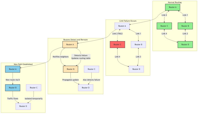
Diagram 12
Routing Protocols:
Routers talk to each other using routing protocols to share information about network topology:
Interior Gateway Protocols (within an organization):
- RIP (Routing Information Protocol): Simple, distance vector, maximum 15 hops
- OSPF (Open Shortest Path First): Link state, builds complete topology map, fast convergence
- EIGRP (Enhanced Interior Gateway Routing Protocol): Cisco proprietary, hybrid approach
Exterior Gateway Protocols (between organizations):
- BGP (Border Gateway Protocol): How ISPs exchange routing information, incredibly complex, runs the entire internet
When a link fails, routers detect it and update their routing tables. They inform their neighbors, who update their tables and inform their neighbors, and so on. Eventually, all routers learn about the change and traffic gets rerouted around the failure.
This process is called convergence, and it typically takes seconds to minutes depending on the protocol and network size.
Why This Matters
Real World Impact
Understanding packet switching is not just academic. It has massive real world implications for performance, reliability, and cost.
Performance Benefits:
| Metric | Circuit Switching | Packet Switching | Why It Matters |
|---|---|---|---|
| Setup Time | 1-10 seconds | None | Instant communication |
| Bandwidth Utilization | 20-40% (typical) | 80-95% | Massively more efficient |
| Sharing | One user per circuit | Thousands per link | Enables internet scale |
| Latency | Low and consistent | Variable | Good for most apps |
| Cost | Very high | Low | Made internet affordable |
Real World Case Study: Netflix
Netflix delivers 15% of global internet traffic. Without packet switching, this would be impossible.
The problem: Stream 4K video to millions of simultaneous users worldwide.
The solution:
- Break video into small chunks (typically 4-10 seconds each)
- Encode each chunk at multiple quality levels
- Store chunks in CDN servers close to users
- Send chunks as packets over the regular internet
- Player buffers packets and adapts quality based on network conditions
Results:
- Serves 230+ million subscribers
- Uses packet switching with adaptive bitrate streaming
- Handles network congestion gracefully (quality drops instead of rebuffering)
- Cost effective (shares internet infrastructure with everyone else)
If Netflix had to establish dedicated circuits to every viewer, the cost would be astronomical and it simply would not work.
Developer Experience Impact:
Understanding packets helps you:
-
Debug network issues faster: When you see "packet loss" in your monitoring, you know exactly what is happening and where to look.
-
Optimize application performance: You can make smart decisions about:
- Payload sizes (avoid packet fragmentation)
- Request batching (reduce overhead from headers)
- Protocol selection (TCP for reliability, UDP for speed)
-
Design better architectures: You understand:
- Why microservices on the same local network perform better
- Why ChatOps needs UDP (real time, bursty traffic)
- Why CDNs improve performance (fewer hops, less latency)
-
Estimate costs and capacity: You can calculate:
- Bandwidth requirements based on packet rates
- Infrastructure needs for scaling
- Cost of data transfer between cloud regions
Trade Offs and Gotchas
When Packet Switching Shines
Packet switching is the foundation of the modern internet, but it is not perfect for everything. Let me show you where it excels and where it struggles.
Use packet switching when:
-
Bursty traffic patterns: Web browsing, API calls, file transfers anything where you send data intermittently. Sharing bandwidth is incredibly efficient here.
-
Many to many communication: When you need any computer to potentially talk to any other computer. Circuit switching could never scale to billions of devices.
-
Resilience is critical: Networks need to survive failures gracefully. Packet switching automatically routes around problems.
-
Cost efficiency matters: Sharing infrastructure dramatically reduces costs. The entire internet exists because packet switching made it affordable.
-
Flexible bandwidth needs: Different applications need different amounts of bandwidth at different times. Packet switching allocates bandwidth dynamically.
When Packet Switching Struggles
Packet switching is not ideal for every situation:
-
Real time voice/video with strict latency requirements: While we have made it work (VoIP, Zoom), packet switching introduces variable latency. Circuit switching provided more predictable latency for traditional phone calls.
-
Constant, high bandwidth streams: If you genuinely need a constant 10 Gbps connection between two points 24/7, a dedicated circuit might actually be more efficient (though you are probably using dedicated fiber, which still uses packet switching under the hood).
-
Ultra low latency trading systems: High frequency trading firms sometimes use dedicated circuits or specialized networks because every microsecond matters.
-
Critical infrastructure: Some industrial control systems use dedicated connections because the unpredictability of packet switching is unacceptable for life safety systems.
Common Mistakes and Misconceptions
Let me address the most common misunderstandings about how data travels across the internet:
Mistake 1: Thinking packets always take the same path
- Why it happens: It feels logical that packets would follow a fixed route
- Impact: Confusion when debugging network issues or seeing different latencies
- Reality: Each packet is routed independently. Different packets in the same data stream can take different paths. Routers make forwarding decisions based on current network conditions.
- How to see it: Use
traceroutemultiple times to the same destination. You will often see different paths.
Mistake 2: Assuming the internet is centrally controlled
- Why it happens: It seems like something this complex must have central coordination
- Impact: Misunderstanding how network failures and routing changes work
- Reality: The internet is completely decentralized. No one owns or controls it. Each Autonomous System (AS) makes its own routing decisions. This is why the internet is so resilient but also why fixing problems can be complex.
- How it works: BGP allows different networks to advertise routes and make independent forwarding decisions.
Mistake 3: Thinking bigger packets are always better
- Why it happens: More data per packet means less overhead, right?
- Impact: Actually causes worse performance due to fragmentation and increased loss probability
- Reality: Networks have MTU limits (typically 1,500 bytes). Packets larger than the MTU get fragmented, which introduces overhead and reliability issues. If any fragment is lost, the entire packet must be retransmitted.
- How to avoid: Use Path MTU Discovery or stick to safe payload sizes (1,400 bytes or less for TCP).
go//  WRONG: Sending huge packets
func sendData(data []byte) {
    // Sending 64KB at once will cause fragmentation
    conn.Write(data) // data is 65536 bytes
}

//  RIGHT: Chunking data appropriately
func sendDataChunked(data []byte) {
    maxChunkSize := 1400 // Safe size that avoids fragmentation
    for i := 0; i < len(data); i += maxChunkSize {
        end := i + maxChunkSize
        if end > len(data) {
            end = len(data)
        }
        chunk := data[i:end]
        conn.Write(chunk)
    }
}
Mistake 4: Ignoring packet loss
- Why it happens: In testing, local networks rarely drop packets
- Impact: Applications crash or hang when deployed to real internet conditions
- Reality: The internet drops packets regularly. 0.1% to 1% packet loss is normal. Your application must handle this gracefully. TCP handles retransmission automatically, but you still need timeouts and error handling.
- How to fix: Always set appropriate timeouts. Test your application with network simulation tools that introduce packet loss.
go//  WRONG: No timeout
conn, err := net.Dial("tcp", "example.com:80")
if err != nil {
    return err
}
// If the network has issues, this hangs forever
data, err := io.ReadAll(conn)

//  RIGHT: Set reasonable timeouts
conn, err := net.DialTimeout("tcp", "example.com:80", 5*time.Second)
if err != nil {
    return err
}
conn.SetDeadline(time.Now().Add(30*time.Second))
data, err := io.ReadAll(conn)
Mistake 5: Not understanding the difference between bandwidth and latency
- Why it happens: People use these terms interchangeably
- Impact: Wrong optimization strategies, disappointed users
- Reality:
- Bandwidth: How much data you can transfer per second (like pipe width)
- Latency: How long it takes for a packet to travel from source to destination (like pipe length)
- You can have high bandwidth but high latency (fat pipe, but long)
- You can have low bandwidth but low latency (thin pipe, but short)
- Why it matters:
- For file downloads: Bandwidth matters most
- For video calls and gaming: Latency matters most
- For web browsing: Both matter (latency for initial request, bandwidth for content)
Mistake 6: Forgetting about the bufferbloat problem
- Why it happens: More buffering seems like it should always help
- Impact: High latency even on fast connections
- Reality: Routers and network devices buffer packets in queues. If buffers are too large, packets can sit waiting for seconds even on a gigabit connection. This creates artificial latency.
- How to fix: Use modern queue management algorithms (like CoDel or fq_codel) and appropriate buffer sizes.
Mistake 7: Assuming packet order is guaranteed
- Why it happens: TCP provides ordered delivery, so people assume packets arrive in order
- Impact: Confusion when working with UDP or examining packet captures
- Reality: IP does not guarantee ordering. Packets can arrive out of order. TCP reorders them before delivering to your application, but if you use UDP or examine raw packets, you will see reordering.
- How to handle: If using UDP, add sequence numbers in your application protocol and handle reordering yourself.
Performance Considerations
| Consideration | Impact | Mitigation |
|---|---|---|
| Packet overhead | 40-60 bytes per packet reduces effective throughput | Use reasonable payload sizes (1,400+ bytes) |
| Router processing delay | Each hop adds 1-10ms of latency | Minimize hops, use CDNs, choose closer servers |
| Queue delays (bufferbloat) | Can add 100ms-1000ms of latency | Use modern queue management, QoS, reduce buffer sizes |
| Packet loss | Triggers retransmission, doubles latency | TCP handles automatically but add application timeouts |
| Out of order delivery | TCP must buffer and reorder | Minimize with single path routing (QUIC, MPTCP) |
| Path MTU issues | Fragmentation or connection failures | Use Path MTU Discovery or safe default (1,400 bytes) |
Security Considerations
Packets can be intercepted: Any router along the path can read packet contents. This is why encryption (TLS/HTTPS) is essential. Never send sensitive data over plain HTTP.
Packets can be spoofed: An attacker can create packets with forged source addresses. This enables DDoS reflection attacks and IP spoofing attacks. Services should validate requests and use authentication.
Packets can be manipulated: A malicious router could modify packet contents. Encryption prevents this, but also consider using integrity checks (like HMAC).
Routing attacks: BGP hijacking allows an attacker to redirect traffic to their own servers. This has happened multiple times at scale. Use authenticated routing protocols (BGP-SEC) and multiple verification methods.
Comparison with Alternatives
How Does Packet Switching Stack Up?
Let me compare packet switching with the alternatives to help you understand why we use it for the internet.
| Approach | Setup Time | Bandwidth Efficiency | Resource Sharing | Resilience | Cost | Best Use Case |
|---|---|---|---|---|---|---|
| Circuit Switching | Seconds | Low (20-40%) | None | Poor | Very High | Traditional phone calls |
| Packet Switching | None | High (80-95%) | Excellent | Excellent | Low | Internet, data networks |
| Message Switching | None | Medium | Good | Good | Medium | Email, store and forward |
| Virtual Circuits | Milliseconds | Medium-High | Limited | Medium | Medium | ATM, MPLS, Frame Relay |
Circuit Switching:
- When it shines: Constant, predictable traffic like traditional phone calls
- Why we moved away: Incredibly wasteful for bursty data traffic, expensive, inflexible
- Modern use: Still used in some telecom backbones, but even voice is moving to VoIP (packet switched)
Message Switching:
- When it shines: Delay tolerant applications like email
- Key difference: Stores entire messages at each hop instead of forwarding immediately
- Why we do not use it for real time: Too much latency from storing complete messages
- Modern use: Email, SMS, some IoT applications
Virtual Circuits (ATM, MPLS, Frame Relay):
- When it shines: Need some guarantees but want better efficiency than circuit switching
- Key difference: Establishes a path through the network, but shares links via statistical multiplexing
- Why it is not dominant: More complex than pure packet switching, internet grew without it
- Modern use: MPLS is common in ISP and enterprise networks for traffic engineering
The winner for the internet: Pure packet switching (connectionless) at the IP layer, with TCP providing virtual circuit like behavior at the transport layer. This gives us the best of both worlds: efficiency and flexibility from packet switching, plus reliability from TCP.
Summary
You have just learned how data actually travels across the internet, from the first packets sent in 1969 to the billions of packets per second flowing through today's networks.
The key insights are:
-
Packet switching revolutionized networking: By breaking data into small, independently routed packets, we created a network that is efficient, resilient, and scalable. This fundamental innovation made the internet possible.
-
Packets are self contained units: Each packet carries addressing information, data, and error checking bits. They travel independently, potentially taking different paths, and get reassembled at the destination.
-
The internet is decentralized: No single entity controls routing. Each router makes independent forwarding decisions based on local information. This distributed approach is why the internet is so robust.
-
Evolution never stops: From ARPANET's four nodes to today's billions of devices, the core concepts remain the same, but we continually optimize for speed, scale, and new use cases.
-
Understanding packets matters: Whether you are debugging network issues, optimizing application performance, or designing distributed systems, knowing how packets flow through the internet gives you superpowers.
Next Steps
Now that you understand how data travels across the internet, here are ways to deepen your knowledge:
-
Read: Learn about TCP's reliability mechanisms and UDP's speed advantages. Understand how routing protocols like BGP keep the internet running.
-
Practice: Use tools like
tcpdump,wireshark,traceroute, andmtrto observe real packets in flight. Capture and analyze packets from your own applications. -
Build: Create a simple packet sniffer in Go. Build a load balancer that distributes packets across multiple servers. Implement a basic chat application using UDP to understand packet ordering challenges.
Resources
- RFC 791: Internet Protocol - The original IP specification
- A Brief History of the Internet (Internet Society)
- How Routing Works - Router requirements RFC
- Wireshark Network Analysis - Book by Laura Chappell
- Related DevSwiftTools blogs: TCP/IP deep dive, UDP explained, HTTP protocols
The internet is one of humanity's greatest engineering achievements. Every time you send a message, stream a video, or load a webpage, billions of packets flow through this elegant system. Now you know how it actually works.